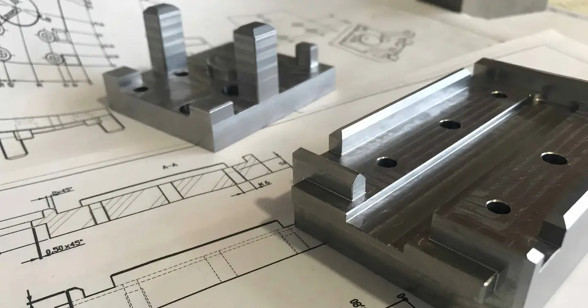
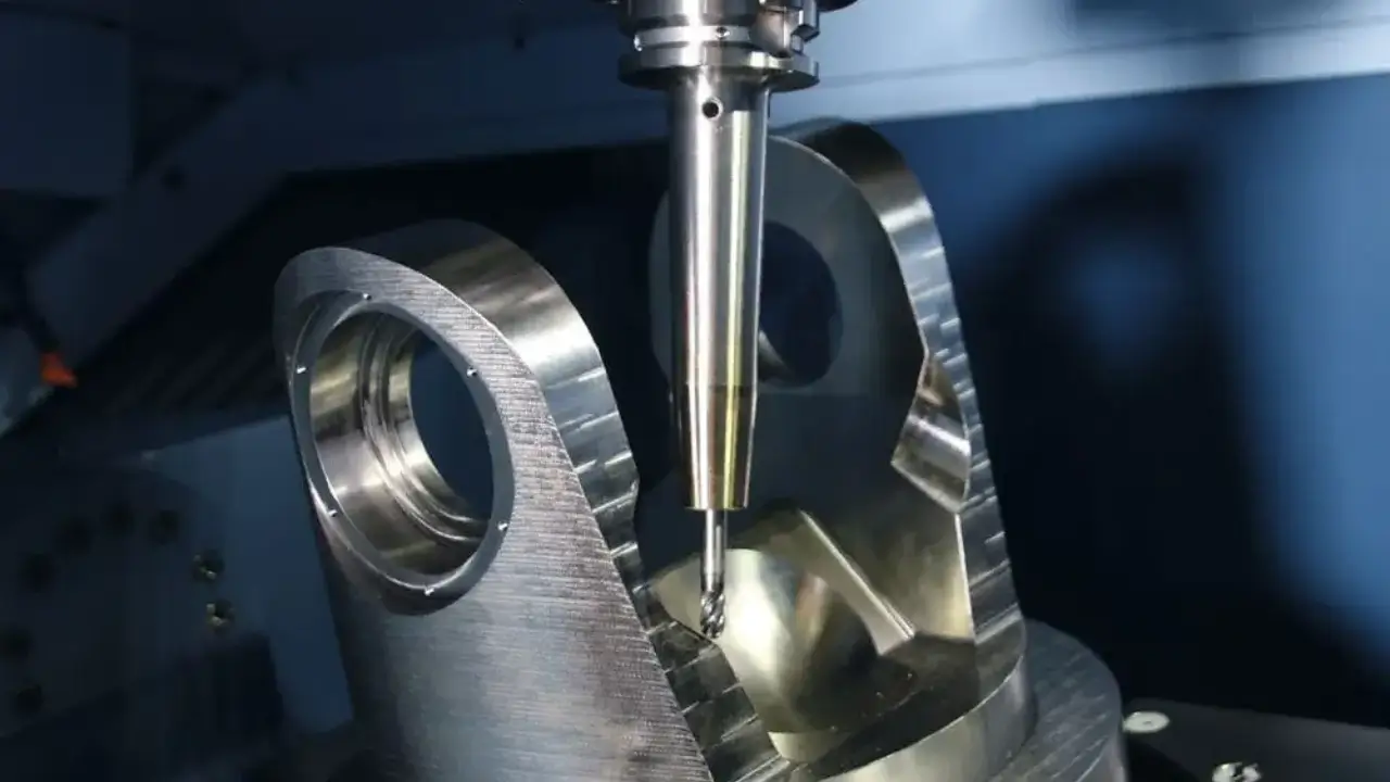
In the realm of CNC machining, precision is the cornerstone of quality. However, achieving absolute perfection in every dimension is not only impractical but also costprohibitive. This is where CNC machining tolerances become indispensable. By defining allowable variations in a part’s dimensions, tolerances ensure functionality while balancing efficiency and cost. In this comprehensive guide, we will delve deep into the world of CNC tolerances, exploring their definitions, types, industry standards, influencing factors, and practical applications. Whether you’re an engineer, designer, or project manager, this guide will equip you with the knowledge to make informed decisions that optimize your CNC projects.

1. What Are CNC Machining Tolerances?
CNC machining tolerances represent the permissible range of variation in a part’s final dimensions, geometric features, or surface finishes. These tolerances are typically denoted using a ± symbol (e.g., ±0.001 inches or ±0.025 mm), indicating that the manufactured part’s size can deviate slightly above or below the nominal measurement. For example, a dimension specified as 10.000 mm with a tolerance of ±0.010 mm means the part is acceptable if it measures between 9.990 mm and 10.010 mm.
Why Tolerances Matter
Tolerances serve several critical purposes in manufacturing:
Functional Consistency: They ensure that parts fit together correctly and perform as intended, even when produced in large quantities.
Cost Efficiency: By allowing minor deviations, tolerances reduce the need for excessively precise (and expensive) machining processes.
Design Flexibility: Tolerances accommodate variations in materials, machine capabilities, and environmental conditions during production.
Without clear tolerances, manufacturers would face significant challenges in meeting both functional requirements and budget constraints.
The Role of Tolerances in CNC Machining
CNC machines are inherently precise, but no machine is flawless. Vibrations, tool wear, thermal expansion, and material inconsistencies can all introduce minor errors. Tolerances account for these unavoidable variations, ensuring that parts remain within acceptable limits for their intended use.
For instance, in automotive manufacturing, a piston must fit perfectly within a cylinder to prevent leaks. A tight tolerance (e.g., ±0.005 mm) ensures this fit, while a looser tolerance might suffice for a noncritical component like a bracket.
2. Types of CNC Machining Tolerances
Understanding the different types of tolerances is essential for accurately specifying requirements in your design. Below is a detailed breakdown of the most common tolerance categories:
2.1 Standard Tolerances
Standard tolerances are predefined, industrywide benchmarks established by organizations like the International Organization for Standardization (ISO), American Society of Mechanical Engineers (ASME), and American National Standards Institute (ANSI). These standards provide a baseline for manufacturers when no custom tolerances are specified.
ISO 2768: This standard outlines general tolerances for linear and angular dimensions, divided into precision grades (e.g., ISO 2768m for medium precision).
ASME Y14.5: Focused on geometric dimensioning and tolerancing (GD&T), this standard defines symbols and rules for controlling form, orientation, and position.
Example: A CNC shop might default to ±0.1 mm for general machining if no specific tolerance is provided, following ISO 2768.
2.2 Bilateral Tolerances
Bilateral tolerances allow deviations in both positive and negative directions from the nominal dimension. They are denoted as ±X, where X is the allowable variation. For example, a dimension of 25.00 mm ±0.05 mm means the part can measure between 24.95 mm and 25.05 mm.
Applications: Bilateral tolerances are common for exterior dimensions where slight variations in either direction do not compromise functionality. They are also simpler to apply in designs, as they require only a single tolerance value.
2.3 Geometric Dimensioning and Tolerancing (GD&T)
GD&T is a sophisticated system that controls not just size but also geometric characteristics such as flatness, straightness, concentricity, and true position. It uses symbols and datums to specify how features should relate to each other.
Key GD&T Symbols:
Flatness (◻): Ensures a surface lies within a specified plane.
Concentricity (◎): Ensures a feature is centered around a datum axis.
Position (Ⓟ): Controls the location of a feature relative to a datum.
Why GD&T Matters: For highprecision parts, such as those in aerospace or medical devices, GD&T ensures proper fit, reduces assembly issues, and enhances overall performance.
2.4 Unilateral Tolerances
Unilateral tolerances permit variation in only one direction from the nominal dimension. They are expressed as +X/Y, where X and Y can be different values. For example, a dimension of 15.00 mm +0.10 mm/0.00 mm means the part must be at least 15.00 mm but no more than 15.10 mm.
Applications: Unilateral tolerances are useful when a part must fit into another component without exceeding a critical dimension. For instance, a shaft designed to fit into a hole might have a unilateral tolerance to ensure it does not become too large.
2.5 Limit Tolerances
Limit tolerances define an explicit range within which a dimension must fall. They are expressed as two values, such as 10.00–10.10 mm, indicating the minimum and maximum acceptable measurements.
Advantages: Limit tolerances are straightforward for inspections and eliminate ambiguity. They are often used in industries where compliance with strict regulations is essential, such as medical or automotive manufacturing.
2.6 Surface Finish Tolerances
While not strictly dimensional, surface finish tolerances specify the allowable roughness or smoothness of a part’s surface. They are denoted using symbols like Ra (arithmetical mean roughness) and are critical for parts requiring tight seals or reduced friction.
Example: A hydraulic cylinder might require a surface finish of Ra 0.8 µm to ensure proper sealing.
3. Industry Standards for CNC Machining Tolerances
To ensure consistency and compatibility across global manufacturing, organizations have established standardized tolerance systems. Below is an overview of the most widely recognized standards:
3.1 ISO Standards
The International Organization for Standardization (ISO) offers several key standards for tolerances:
ISO 2768: Specifies general tolerances for linear and angular dimensions, dividing them into four precision grades (f, m, c, v) for different applications.
ISO 1101: Focuses on geometric tolerances, including form, orientation, and position.
3.2 ASME Standards
The American Society of Mechanical Engineers (ASME) provides standards like:
ASME Y14.5: The primary standard for GD&T in the United States, defining symbols and rules for geometric tolerancing.
ASME Y14.41: Addresses the digital definition of product geometry, ensuring clarity in 3D models.
3.3 ANSI Standards
The American National Standards Institute (ANSI) collaborates with ASME to publish standards like:
ANSI B4.2: Specifies preferred limits and fits for cylindrical parts, guiding designers in selecting appropriate tolerances for mating components.
3.4 Other Regional Standards
JIS (Japan): Japanese Industrial Standards, such as JIS B0401, outline tolerances similar to ISO standards.
DIN (Germany): Deutsche Institut für Normung standards, like DIN 7184, focus on dimensional and geometric tolerances.
Why Standards Matter: Adhering to these standards ensures that parts can be manufactured and inspected consistently across different facilities and countries. It also simplifies communication between designers, manufacturers, and suppliers.
4. Factors Influencing CNC Machining Tolerances
Several variables affect the achievable tolerances in CNC machining. Understanding these factors is crucial for setting realistic expectations and optimizing your project:
4.1 Material Properties
The type and properties of the material being machined play a significant role in determining tolerances:
Hardness: Harder materials like titanium or stainless steel are more challenging to machine and may require tighter tolerances to account for tool wear and deformation.
Thermal Expansion: Materials with high thermal expansion coefficients (e.g., aluminum) can expand and contract during machining, affecting dimensional accuracy.
Machinability: Softer materials like plastics or aluminum allow for looser tolerances, while brittle materials like cast iron may require stricter controls to prevent cracking.
4.2 CNC Machine Capabilities
The precision of the CNC machine and its components directly impacts achievable tolerances:
Machine Rigidity: A rigid machine frame minimizes vibrations, enabling tighter tolerances.
Axis Accuracy: Highend machines with linear scales can achieve accuracies as tight as ±0.0025 mm.
Tooling: The quality of cutting tools (e.g., carbide vs. highspeed steel) and their wear patterns affect dimensional consistency.
4.3 Part Design and Geometry
Complex part geometries can complicate machining and influence tolerances:
Feature Size: Smaller features (e.g., tiny holes or thin walls) are harder to machine precisely, often requiring tighter tolerances.
Aspect Ratios: Deep holes or narrow slots may introduce tool deflection, necessitating adjustments in tolerances.
Surface Finish Requirements: A smoother surface finish often demands tighter tolerances to ensure uniformity.
4.4 Environmental Factors
Conditions in the machining environment can affect accuracy:
Temperature Fluctuations: Changes in temperature can cause the machine, tools, or workpiece to expand or contract, leading to dimensional errors.
Humidity: Moisture can affect materials like wood or certain plastics, altering their dimensions.
Vibration: External vibrations from nearby machinery can degrade machining precision.
4.5 Machining Processes
Different CNC processes have varying levels of precision:
Milling: Typically achieves tolerances of ±0.05 mm to ±0.01 mm.
Turning: Can reach tighter tolerances, around ±0.01 mm to ±0.005 mm.
Grinding: A finishing process that can achieve extremely tight tolerances (e.g., ±0.001 mm) for highprecision parts.
5. How to Choose the Right Tolerance for Your Project
Selecting the optimal tolerance requires a balance between precision, functionality, and cost. Below is a stepbystep guide to help you make informed decisions:
5.1 Define the Part’s Function
Start by identifying which dimensions are critical to the part’s performance:
Critical Features: Mating surfaces, holes for fasteners, or components that interact with other parts require tight tolerances.
NonCritical Features: Decorative elements or structural supports may tolerate looser specifications.
Example: A gear tooth profile demands tight tolerances for smooth operation, while a bracket’s overall length might allow more variation.
5.2 Consult Tolerance Standards
Refer to industry standards (e.g., ISO 2768, ASME Y14.5) to establish a baseline. These standards provide recommended tolerance ranges for different applications and materials.
5.3 Evaluate Material and Process Limitations
Consider the material’s machinability and the capabilities of your CNC shop:
Material Constraints: Hard materials may require looser tolerances to avoid tool damage.
Machine Precision: Ensure your shop’s equipment can meet the specified tolerances. Highend machines justify tighter tolerances, while older equipment may need more lenient specs.
5.4 Collaborate with Your Machining Provider
Engage with your CNC machining partner early in the design process. Their expertise can help you:
Optimize Designs: Identify features that can be relaxed to reduce costs.
Understand Tradeoffs: Clarify how tolerance choices impact manufacturability and budget.
5.5 Conduct a Tolerance Analysis
Use tools like worstcase analysis or statistical tolerance analysis to determine how cumulative variations in dimensions will affect the part’s functionality. This ensures that even with allowable deviations, the part will perform as intended.
5.6 Avoid OverEngineering
Resist the urge to specify unnecessarily tight tolerances. Overly strict requirements can:
Increase Costs: Tighter tolerances demand more expensive processes and inspections.
Delay Production: Machinists may need additional time to meet precision goals.
Instead, focus on tolerances that align with the part’s actual performance needs.
6. The Impact of Tolerances on Project Costs
Tolerances directly influence the cost of CNC machining. Understanding this relationship is key to budget optimization:
6.1 Why Tight Tolerances Are Expensive
Advanced Machinery: Achieving tight tolerances (e.g., ±0.005 mm) requires highprecision CNC machines, which are more expensive to purchase and maintain.
Specialized Tooling: Highquality cutting tools with superior wear resistance are often necessary for precise machining.
Labor Intensity: Machinists need more time to set up machines, monitor processes, and make adjustments to meet tight specs.
Quality Control: Stringent inspections using coordinate measuring machines (CMMs) or optical comparators add to labor and equipment costs.
6.2 Cost vs. Tolerance Tradeoffs
To illustrate the cost impact, consider the following examples:
Loose Tolerance (±0.1 mm): Suitable for noncritical parts, requiring minimal setup and inspection.
Medium Tolerance (±0.02 mm): Demands better equipment and careful monitoring, increasing costs by 10–20%.
Tight Tolerance (±0.005 mm): May double or triple costs due to specialized machinery, tooling, and quality checks.
6.3 Strategies to Reduce Costs Without Sacrificing Quality
Relax NonCritical Tolerances: Allow looser specs for features that don’t affect functionality.
Standardize Designs: Use common tolerances across multiple parts to streamline production.
Optimize Material Selection: Choose materials that are easier to machine within the required tolerances.
7. When Loose Tolerances Are Acceptable
While precision is often essential, there are scenarios where looser tolerances are not only acceptable but preferable:
7.1 Cosmetic Components
Parts where appearance is the primary concern (e.g., decorative brackets, housings) may not require tight tolerances. Slight variations in dimensions are unlikely to affect their aesthetic appeal.
7.2 NonFunctional Features
Features that do not interact with other components (e.g., reinforcing ribs in a plastic enclosure) can often tolerate looser specs.
7.3 CostCritical Projects
When budget constraints are tight, relaxing tolerances can significantly reduce machining costs without compromising the part’s intended use.
7.4 Prototyping and LowVolume Production
During prototyping, the focus is on testing functionality rather than perfection. Loose tolerances allow for faster iterations and costeffective adjustments.
8. How Our Company Controls CNC Tolerances
At Jxd Machining, we prioritize precision and consistency in every project. Our rigorous approach to tolerance control ensures that parts meet even the most demanding specifications:
8.1 StateoftheArt Equipment
We invest in highprecision CNC machines equipped with advanced features like:
Linear Encoders: Provide realtime feedback to maintain positioning accuracy.
Thermal Compensation Systems: Adjust for temperatureinduced expansions to minimize errors.
MultiAxis Machining: Enables complex geometries with tight tolerances.
8.2 Experienced Engineering Team
Our team of skilled engineers collaborates with clients to:
Optimize Designs: Review CAD models to identify tolerance adjustments that improve manufacturability.
Select Materials: Recommend materials that balance performance and machinability.
Define GD&T Requirements: Apply geometric tolerances to ensure proper fit and function.
8.3 Stringent Quality Assurance Processes
We implement a multilayered quality control system:
InProcess Inspections: Machinists use precision tools (e.g., calipers, micrometers) to verify dimensions during production.
PostProcess Testing: Final parts are inspected using CMMs and optical scanners to ensure compliance with specifications.
Statistical Process Control (SPC): We monitor machining processes to detect trends and prevent defects proactively.
8.4 Transparent Communication
We keep clients informed at every stage:
Tolerance Reports: Provide detailed documentation of measured dimensions and compliance.
Design Feedback: Offer suggestions to adjust tolerances if they are impractical or unnecessarily costly.
8.5 Continuous Improvement
We regularly upgrade our processes and training to stay ahead of industry advancements:
Machine Calibration: Regularly service and calibrate equipment to maintain peak performance.
Employee Training: Train staff on the latest machining techniques and tolerance standards.
9. Case Studies: RealWorld Tolerance Applications
To illustrate the practical application of tolerances, consider these scenarios:
9.1 Automotive Component
A car manufacturer requires a piston with a diameter of 85.00 mm. A tight tolerance of ±0.01 mm ensures a precise fit within the cylinder, minimizing leaks and maximizing engine efficiency.
9.2 Medical Device
A surgical instrument’s hinge mechanism demands a flatness tolerance of 0.02 mm to ensure smooth operation. GD&T is used to control the orientation of mating surfaces.
9.3 Consumer Electronics
A smartphone housing’s cosmetic finish allows a looser tolerance of ±0.1 mm, reducing production costs while maintaining an acceptable appearance.
10. Conclusion
CNC machining tolerances are a vital tool for balancing precision, functionality, and cost in manufacturing. By understanding the types of tolerances, industry standards, and influencing factors, you can make informed decisions that optimize your projects. Whether you need tight tolerances for a highperformance aerospace component or looser specs for a costeffective prototype, partnering with an experienced CNC machining provider like [Your Company Name] ensures expertise and reliability.
Ready to elevate your next project with precisionengineered CNC parts? Contact us today to discuss your tolerance requirements and discover how we can bring your designs to life with unmatched quality and efficiency.
This expanded guide provides a deep dive into CNC machining tolerances, offering actionable insights for engineers, designers, and manufacturers. By leveraging this knowledge, you can navigate the complexities of tolerance specification and achieve success in your CNC projects.

